
Abstract
Onboard motorsport video is captured by phones and action cameras mounted in the airflow. At racing speed the dominant sound is not the engine but broadband aerodynamic wind, which buries the engine note that gives a clip its emotional impact. Conventional noise reduction treats the wind as stationary hiss and, in removing it, strips the engine with it.
This paper presents a hybrid approach: a harmonic-sieve DSP filter whose frequency lock is driven by the vehicle's telemetry and gearing model. The sieve treats the engine as a moving harmonic comb, keeping the recorded magnitude and phase at each harmonic and rejecting the broadband wind between them, and a final stage restores loudness. The hard part is placing that comb on the true engine fundamental as it sweeps with RPM. The hybrid solves it by deriving the fundamental from the synchronized GPS speed and the car's homologated gear ratios, with the audio itself selecting among the few physically legal candidates. Suppression also scales with speed, tightening on the straights where wind is worst.
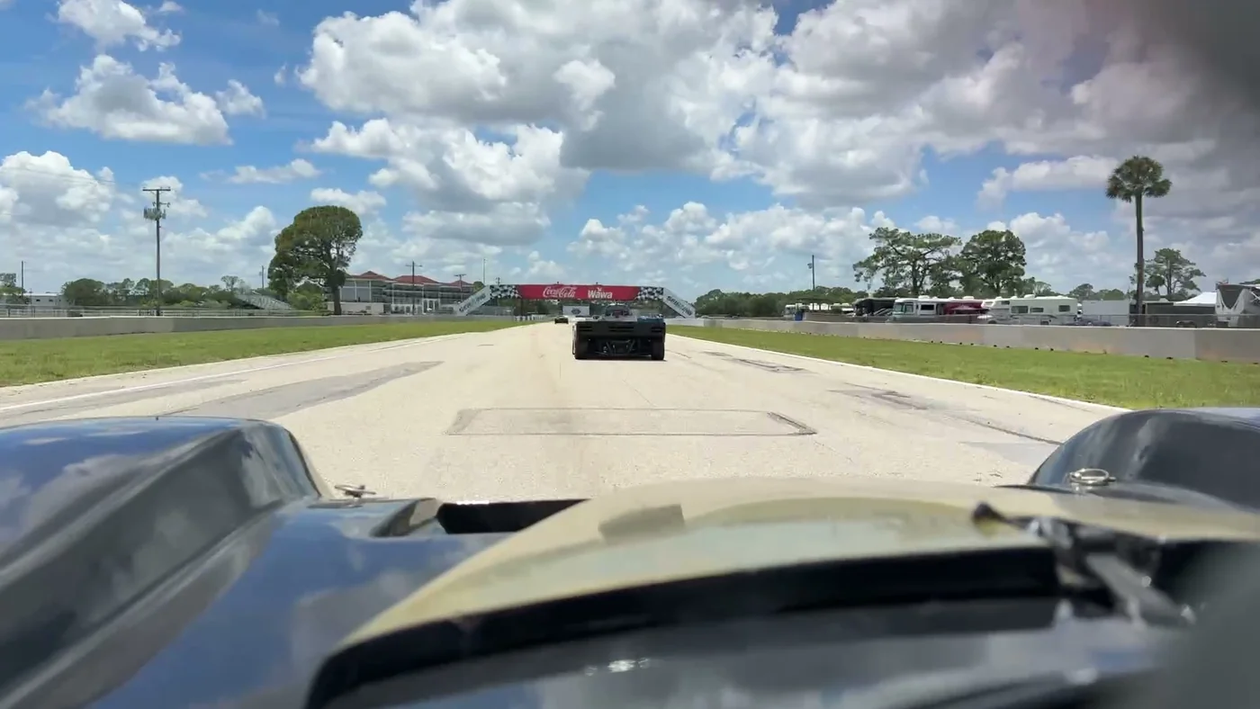
We validate the method on a real 13-second onboard segment from Sebring International Raceway in a Spec Racer Ford. The hybrid lock places the fundamental on the correct gear throughout the clip, recovering the current gear as a by-product, and the resulting filter removes roughly 10 to 22 dB of wind per octave band, over a between-harmonic rejection floor the design sets to 20 to 30 dB, while holding overall loudness flat. The combination of signal processing and vehicle data does what neither does alone: it makes the engine, not the wind, the thing you hear.
Overview
The speed-adaptive harmonic sieve is a real-time-capable, allocation-free audio processor that runs at video-export time on generated clips. It is not a generic denoiser; it is a model-based enhancer that knows what an engine looks like in the frequency domain and uses that structure to separate engine from wind.
- Primary function: suppress aerodynamic wind noise in onboard race audio while preserving the recorded engine and exhaust timbre.
- Frequency lock: hybrid. The synchronized GPS speed and the car's gear ratios propose the engine fundamental; the audio selects among the physically legal candidates. Audio-only tracking is the fallback when no car data is available.
- Non-goals: it does not synthesize or replace the engine sound, does not run on the raw on-track recording, and does not require a tachometer or any wired vehicle interface.
The design intent is captured in one sentence: keep the engine's harmonics exactly as recorded, and remove everything between them, harder when the car is going faster.
Background and problem statement
Aerodynamic noise at a microphone grows steeply with airspeed, roughly with the square of velocity, and is broadband: it has energy at essentially every frequency. The engine, by contrast, is sparse in frequency. A four-stroke engine produces a pressure pulse each time a cylinder fires, so its sound is a harmonic series: a firing fundamental and a stack of overtones at integer multiples of it. The fundamental sweeps up and down with RPM.
This structural difference, broadband wind versus sparse harmonic engine, is the entire opportunity. A filter that passes only the narrow neighborhoods around the engine's harmonics, and rejects the wide gaps between them, removes most of the wind while keeping most of the engine. The difficulty is that the harmonics move as the driver works the throttle and gearbox, so the filter must know where they are frame by frame. Estimating that from the wind-dominated audio alone is unreliable, so this paper's central idea is to take the answer from the vehicle instead: the car's gearing and the synchronized GPS speed tell us the engine's fundamental directly.
Requirements
- FR-1 Suppress broadband wind noise while preserving recorded engine and exhaust harmonics.
- FR-2 Track the engine firing fundamental as it sweeps with RPM, frame by frame.
- FR-3 Drive suppression strength from the clip's synchronized GPS speed where available.
- FR-4 Expose a single user-facing strength control; never require manual frequency tuning.
- FR-5 Apply only to generated clips; never modify the raw on-track recording.
- FR-6 Produce loudness-matched output so the enhanced clip is not quieter than the source.
- FR-7 Degrade gracefully: with no telemetry, run a sensible default; with no engine present, do no harm.
| Item | Target | Notes |
|---|---|---|
| Algorithmic latency | About 32 ms | FFT size minus hop at 48 kHz; applied uniformly, within A/V sync tolerance offline |
| Hot-path allocation | Zero | All working buffers pre-allocated per export |
| Frequency resolution | About 23 Hz per bin | 2048-point STFT at 48 kHz resolves the harmonic spacing |
| Throughput | Faster than real time | Offline export; one DSP instance per clip |
Architecture
The enhancement is orchestrated by the clip builder, carried on a per-clip export request, and realized by a processing stage that wraps a single shared signal-processing core. The core holds one harmonic sieve per audio channel, followed by a running loudness match and a soft limiter.
- Clip builder: resamples the session telemetry over each clip's time window to a fixed-rate GPS speed profile and attaches it, with the strength setting, to the export request.
- Processing stage: reads the clip's audio as PCM, streams it through the shared signal-processing core, and writes the enhanced audio back into the clip.
- Signal-processing core: owns one harmonic sieve per channel, tracks input-versus-output level with a slow follower to restore the loudness the sieve removes, and applies a hyperbolic-tangent soft limiter to guarantee a safe ceiling.
- Harmonic sieve: the single-channel heart of the system: short-time Fourier analysis, fundamental tracking, harmonic mask construction, spectral masking of the original complex spectrum, and weighted overlap-add resynthesis.
The algorithm
For a four-stroke engine each cylinder fires once every two crankshaft revolutions. With Ncyl cylinders, the firing fundamental in hertz is
f0 = Ncyl × RPM / 120
For a four-cylinder this reduces to f0 = RPM / 30, so 6,000 RPM gives a 200 Hz tone. The engine's energy concentrates at f0 and its integer multiples 2f0, 3f0 and so on. The sieve's job each frame is to find f0 and keep only those multiples.
Once f0 is known, the sieve places a narrow Gaussian "tooth" at every harmonic k·f0 up to the low-pass corner. The teeth define where the original spectrum is kept. Everywhere else the mask falls to a small reject floor: the controlled fraction of the original that survives between harmonics. The full mask is the floor plus the teeth, multiplied by a band-limiting shape that removes sub-bass rumble below 60 Hz and high-frequency air above the speed-dependent low-pass corner.
Critically, the mask multiplies the original complex spectrum, not a synthesized one. Because both magnitude and phase at each harmonic are the recorded values, the output is the real engine, with its true timbre, rasp and exhaust character, not a buzzy reconstruction. A five-bin frequency smoothing removes isolated artifact bins, and a temporal smoothing across frames lets the mask glide as the harmonics move, preventing the warbling that abrupt per-frame masks produce.
How it works, step by step
- Slice the sound. The audio is cut into short, overlapping slices of about 40 milliseconds, and each slice is turned into a spectrum, the same picture a graphic-equalizer display shows. Working slice by slice lets the filter follow the engine as its note rises and falls.
- Find the engine's note. The firing fundamental is set by the rev counter and the cylinder count, and is found by the hybrid lock described below, from the car and GPS speed, not guessed from the wind-filled sound.
- Turn speed into one dial. Wind gets louder with speed, so the filter works harder when the car is faster. The GPS speed becomes a single dial from 0 to 1: dial = (speed − 30) / (95 − 30), kept within 0 to 1. At 30 mph or below the dial reads 0 (gentlest); at 95 mph or above it reads 1 (strongest).
- Build a comb-shaped filter. The filter keeps a narrow band around the engine note and each of its multiples, the teeth of a comb, and turns everything in between down to a small leftover level, the floor. It also trims the deep rumble below 60 Hz and the high hiss above roughly 4 to 5 kHz. As the dial rises, the teeth get narrower and the floor drops lower.
- Keep the real engine, not a copy. The comb is applied to the original recording, so the engine's harmonics pass through with their true tone untouched. At the default setting the floor removes roughly 20 dB of the wind between harmonics at low speed and 30 dB at high speed.
- Smooth so it does not warble. The filter is blurred slightly across neighbouring frequencies and across time, so as the engine note slides the comb glides with it instead of flickering.
- Put the volume back. Removing wind makes the clip quieter, so a final stage compares the level before and after and gently raises the result back to the original loudness, with a soft ceiling so nothing distorts.
Speed adaptivity
Wind grows with speed, so the sieve's aggressiveness is driven by the clip's GPS speed. Three things move together as speed rises from 30 mph (gentlest) to 95 mph (most aggressive): the reject floor closes, so less wind survives between harmonics; the harmonic teeth narrow, so each pass-band is tighter around its harmonic; and the low-pass corner drops from 5.5 kHz toward 3.8 kHz, removing more high-frequency air where there is little engine content.
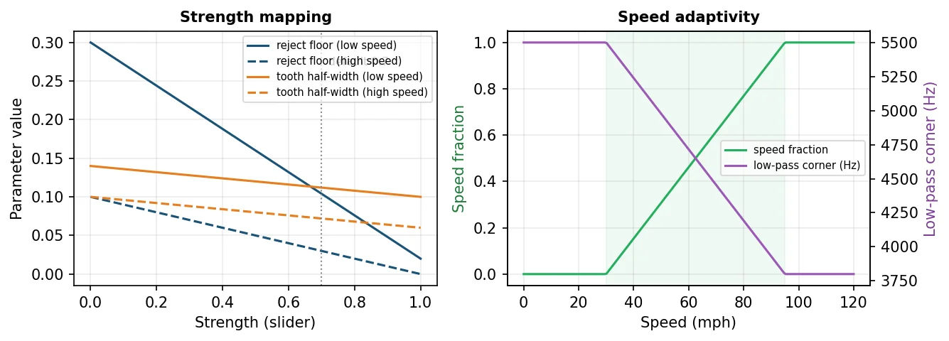
A single strength slider sets the overall envelope; speed modulates within it. At the default strength of 0.7, the between-harmonic floor ranges from about 0.10 at low speed (roughly −20 dB) to about 0.03 at high speed (roughly −30 dB), so the wind in the gaps is attenuated more exactly when there is more of it.
Implementation
A single signal-processing core implements the sieve, the loudness match and the limiter, and that one implementation is shared everywhere the feature runs. During offline clip generation the host streams the clip's decoded audio through the core frame by frame and writes the enhanced result back into the clip; the raw on-track recording is never touched. Because the sieve is a streaming, block-based design with all working memory pre-allocated, the core runs without allocation on its hot path and is comfortably faster than real time for export, while remaining structured so it could run on a real-time audio thread if needed.
A desktop harness runs the identical core over a WAV file so a parameter change can be auditioned and measured on a workstation before it is adopted.
The hybrid frequency lock
The core of the method is where it gets the engine fundamental, and the answer is not "from the audio" but from the vehicle: the user selects their exact car, and the clip carries synchronized GPS speed. Together these place the fundamental from physics, and the audio is used only to choose among a few physically legal options. Telemetry and gearing constrain; the DSP refines.
Tier 1, logged RPM. Sessions from sim platforms, data loggers or vehicle interfaces already carry RPM. Combined with the cylinder count from the car profile, the fundamental is exact. No tracking, no octave errors.
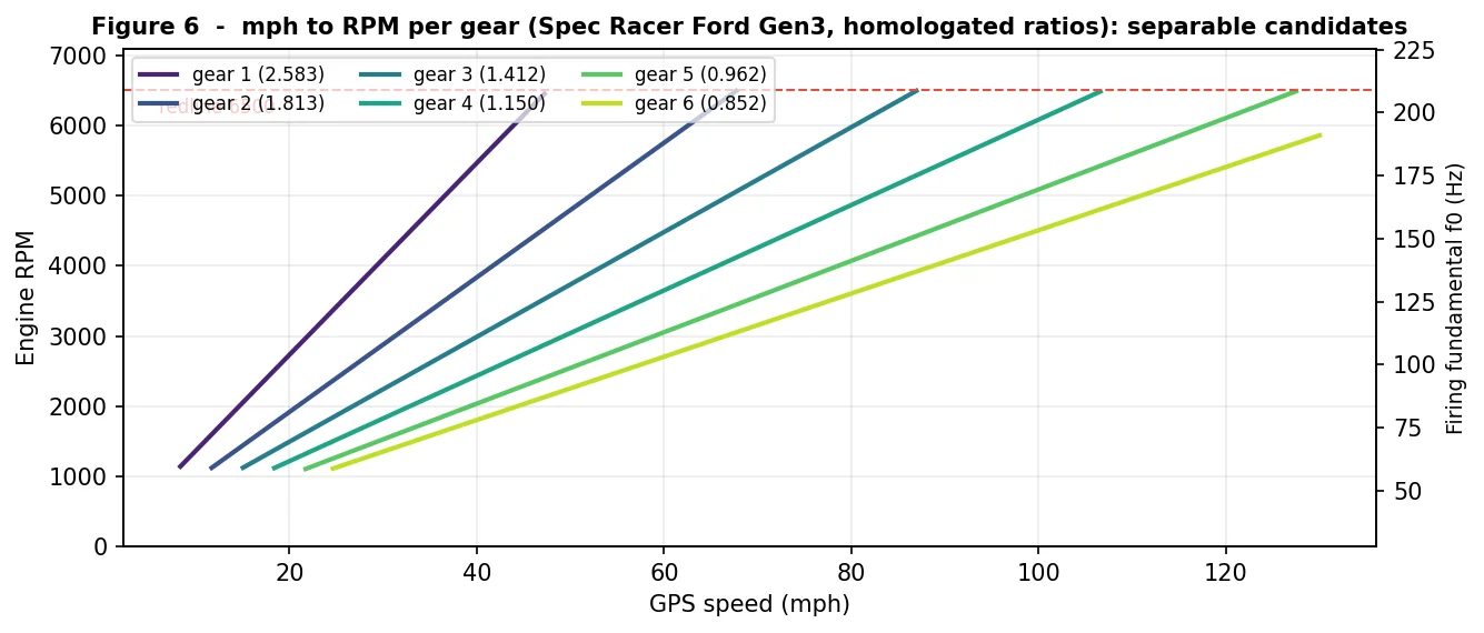
Tier 2, GPS speed plus gear model. For the common phone-only clip there is no RPM channel, but speed v (mph) maps to a small set of candidate RPMs, one per gear g, through the drivetrain, with tire diameter d (inches), final drive rfinal and gear ratio rg:
RPMg = v × 1056 × rfinal × rg / (π × d)
The winning gear is the candidate whose fundamental best matches the local harmonic energy, subject to idle ≤ RPMg ≤ redline. Because there are only six gears and their predicted fundamentals are well separated at any given speed, the problem changes from "estimate a pitch buried in wind" to "pick one of six physically legal answers." The winning candidate also reveals the current gear as a free by-product.
The Spec Racer Ford Gen3 is an ideal worked example because the class is strictly homologated: every car runs the same sealed drivetrain, so these numbers are exact, not estimated.
| Parameter | Value |
|---|---|
| Gearbox | SADEV SRF-3 six-speed sequential |
| Gear ratios (1st to 6th) | 2.583, 1.813, 1.412, 1.150, 0.962, 0.852 |
| Final drive | 3.571 (25:7 ring and pinion) |
| Driven (rear) tire | 205/60R-13, about 22.7 in overall diameter |
| Front tire | 185/60R-13 |
| Cylinders / cycle | 4 / four-stroke |
Results
All results come from a single real recording: a 13-second onboard segment from the front straight of the Sebring Short Course in Steve Spano's 2016 SCCA Spec Racer Ford Gen3, captured on a phone camera. Over the segment the car runs flat out at 95 to 115 mph, then brakes hard to about 17 mph for the corner, a single clip that exercises the full speed-adaptive range.
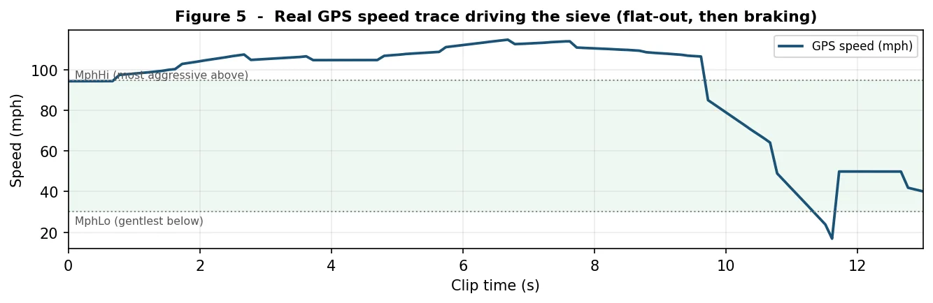
The locked fundamental rides the correct gear across the clip: 120 to 194 Hz (about 3,600 to 5,800 RPM for this four-cylinder) on the straight in fifth and sixth gear, then dropping cleanly through the downshifts into the corner. The current gear falls out of the selection as a free by-product: fifth and sixth down the front straight, exactly as driven.
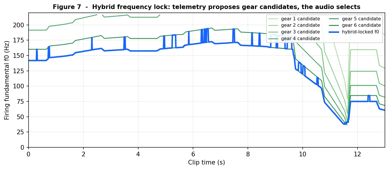
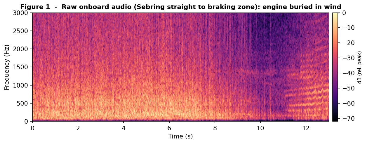
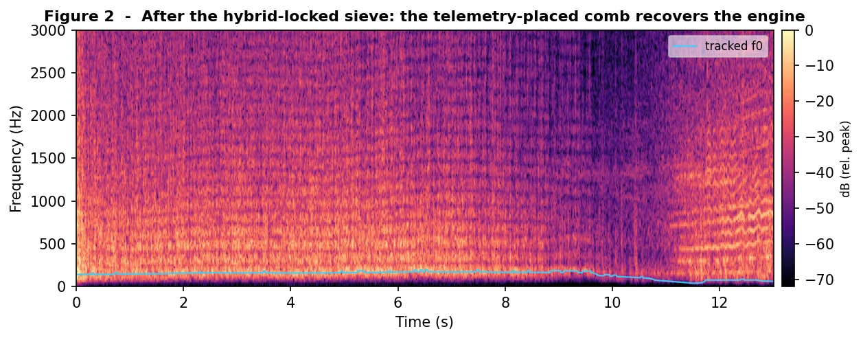
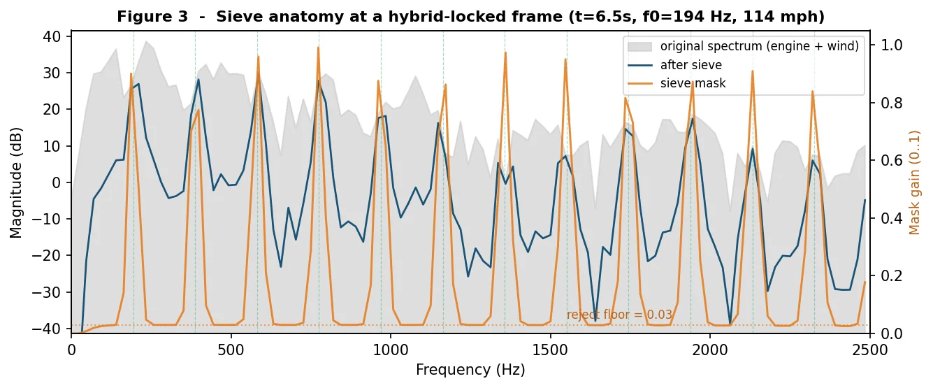
With the comb placed correctly by the hybrid lock, the sieve removes energy in every octave band: most at the extremes, where the band limit cuts sub-bass rumble and high-frequency air, and a strong, steady amount through the mid bands where the comb does its work.
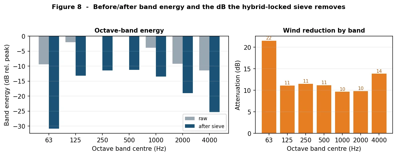
| Octave band (Hz) | 63 | 125 | 250 | 500 | 1000 | 2000 | 4000 |
|---|---|---|---|---|---|---|---|
| Raw (dB rel. peak) | −9.4 | −2.1 | 0.0 | −0.1 | −3.8 | −9.2 | −11.5 |
| After sieve (dB rel. peak) | −30.9 | −13.2 | −11.5 | −11.3 | −13.5 | −19.0 | −25.3 |
| Reduction (dB) | 21.5 | 11.1 | 11.5 | 11.2 | 9.7 | 9.8 | 13.8 |
These are the changes the mask itself applies; a final loudness-match stage then restores overall level so the enhanced clip is not quieter than the source. Because the comb sits on the real engine, it also rejects between harmonics more than on them: a positive comb selectivity of about +1.8 dB on the straight (and +2.2 dB over the clip), versus the near-zero selectivity that results when a fundamental is placed incorrectly.
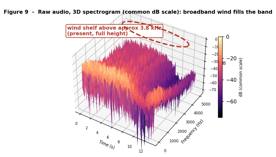
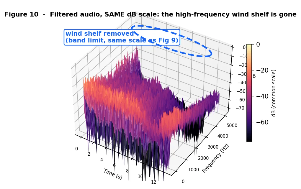
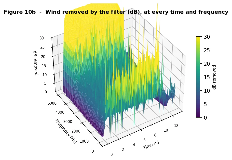
| Metric | Value (this clip) | Source |
|---|---|---|
| Segment duration | 13.0 s | Extracted audio |
| Speed range | 17 to 115 mph | GPS telemetry |
| Locked fundamental on the straight | 120 to 194 Hz (3,600 to 5,800 RPM) | Telemetry + gears |
| Gear recovered on the straight | 5th and 6th | Hybrid selector |
| Broadband wind reduction | 10 to 22 dB per octave | Measured |
| Comb selectivity on the straight | +1.8 dB (between vs on harmonics) | Measured |
| Between-harmonic rejection (design floor) | 20 to 30 dB | Mask reject floor |
| Algorithmic latency | About 32 ms | STFT configuration |
Verification
Successful build and integration is the first gate; validation is by audition and measurement rather than a unit-test suite. The desktop harness runs the identical core over a WAV and reports the RMS level change before and after, so a parameter change can be measured, not just heard. The same harness prints an averaged power spectrum, octave-band energy and tonal-peak prominence to confirm whether residual energy is broadband wind or a tonal resonance. Every figure in the paper was generated by a faithful numerical port of the same core, driven by the real recording and telemetry.
Conclusions
The result is a hybrid: a harmonic-comb DSP filter whose frequency lock comes from the vehicle's telemetry and gearing rather than from the wind-dominated audio. That pairing is what makes it work. The comb knows how to separate a sparse harmonic engine from broadband wind, but only if it is placed correctly; the gear model plus GPS speed place it correctly, and the audio confirms the choice. Neither half suffices alone: telemetry has no idea what to remove, and audio alone cannot reliably find the engine in the wind.
On the real Sebring clip the hybrid lock tracked the engine on the correct gear throughout, and the filter removed 10 to 22 dB of wind per octave while preserving the recorded engine and holding loudness flat. The takeaway is simple: the best way to improve a wind filter was not a better filter, but giving it the car's own data to aim with.
Constraints and limitations
- The hybrid needs drivetrain data. Gear ratios, final drive, tire diameter and cylinder count must be present in the car database. When they are absent the method falls back to audio-only tracking, which is less reliable in heavy wind.
- The speed-to-RPM map is a tight prior, not exact. Tire wear and pressure, drivetrain lash, clutch slip during shifts and wheelspin shift the mapping slightly; this is why the audio still selects among gear candidates rather than the RPM being trusted blindly.
- Selectivity is bounded by mask smoothing. With the comb correctly placed, between-harmonic selectivity is positive but still short of the 20 to 30 dB design floor, because the mask is deliberately smoothed in time and frequency to avoid warble.
- Uniform latency. The roughly 32 ms processing latency is applied to all audio and is within A/V sync tolerance for offline export.
Future work
- Roll the hybrid frequency lock into the live export path, with logged RPM used directly when present (sim, data logger, OBD) and the gear model used otherwise.
- Add gear-state hysteresis and surface the recovered gear as a displayed telemetry channel.
- Relax the mask's temporal and frequency smoothing now that the fundamental is reliable, to realize more of the design's between-harmonic rejection.
- Extend the car database so the drivetrain fields are present for every selectable car.
Author contributions
Steve Spano: product direction, domain expertise and the key conceptual insight. Steve framed the real problem (wind ruins otherwise great onboard clips), set the constraint that the raw recording must never be altered, and drove the central idea: use the vehicle's own data, the exact selected car and the synchronized GPS speed, to predict the engine fundamental from physics rather than guess it from noisy audio. He also supplied the real Sebring recording, the telemetry and the homologated drivetrain data used to validate the method.
Claude (Anthropic, via Claude Code): signal-processing design and implementation. Claude designed the harmonic-sieve realization (STFT analysis, fundamental tracking, comb-mask construction over a speed-dependent reject floor, complex-spectrum masking and weighted overlap-add resynthesis), implemented the allocation-free core and its integration into the clip pipeline, built the speed-adaptive parameter mapping and loudness match, created the offline analysis harness, and produced the experiments on the real data and the report.