
The bottle that plays itself
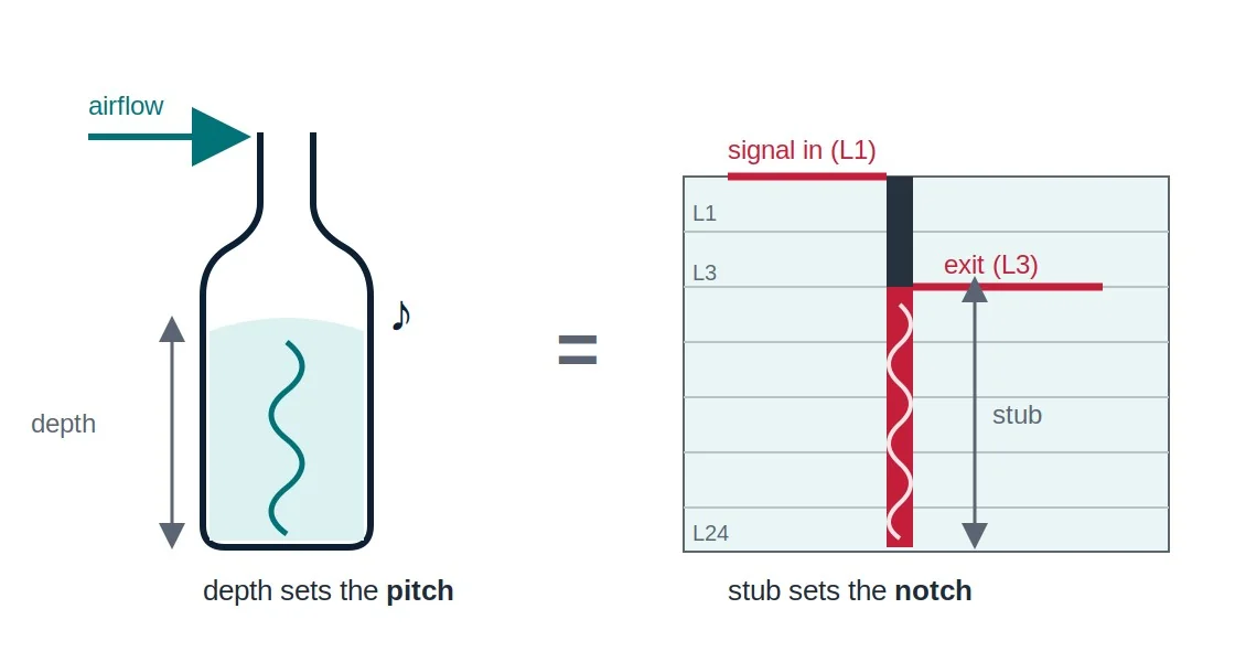
Blow across the mouth of an empty bottle and it plays a note. You didn't add anything to the bottle. The note was always in there: a column of air with a closed end, waiting for energy at the right frequency to come along and wake it up. The pitch is set entirely by the depth of the bottle. Nobody tuned it, because the geometry did that all by itself.
I think about that bottle every time I look at a thick backplane stackup, because every un-back-drilled via in the board is one: a resonant cavity you manufactured by the thousand, at no extra charge. And at 10 Gbps, your signal is the person leaning over the top, blowing.
Twenty thousand errors in thirteen trillion bits
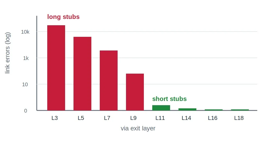
We were midway through hardware bring-up on a 10GBASE-KR backplane when the trouble showed up. Most of the links ran clean, but a handful were throwing intermittent errors. The links were not dead; dead would have been kinder. The worst counters showed on the order of twenty thousand errors against thirteen trillion good bits. Do the division and that comes out to roughly one error per billion bits, which is a link that works 99.9999999% of the time and still fails. There is no probe setting for "mostly fine."
So we pulled the error counters per port and lined them up against the routing, and the pattern fell out in one pass: the failing links were the ones routed on the upper layers of the board, while the links routed deep in the stackup ran clean. The failing links used the same connectors, the same drivers, and the same trace lengths as the clean ones. The only variable that tracked the errors was how far down the barrel the signal turned off the via and headed for the connector. That correlation is the entire diagnosis, if you know how to read it.
The dead end that rings
A signal traveling down a via doesn't know where your trace exits. It fills the whole barrel. Route out on layer 3 of a roughly 100-mil board and the signal leaves near the top, and the ninety-some mils of plated copper below the exit is a stub: a conductive dead end that is faithfully connected and goes nowhere. Energy runs down that stub, hits the open bottom, and reflects back up, arriving late and out of phase with the signal that went straight through.
At low data rates nobody notices, because the stub is short compared to the wavelengths involved and the reflection smears into nothing. But a stub is a quarter-wave resonator. Like the bottle, its depth picks a frequency, and at that frequency it stops being a harmless dead end and starts being a notch filter. You have parked that filter, with some precision, on top of your own data.
The working rule of thumb is via stubs under about 30 mils at 10 Gbps, shrinking as the rate climbs. Ours, on the upper route layers, were about 3x that. Nothing exotic was wrong with those links. Every one of them simply ran through a bottle tuned to drink exactly the band we were transmitting in, while the lower-layer routes exited near the bottom of the barrel, left almost no stub behind, and never heard the note at all.
The gigabit link hiding in your 50 MHz clock
The bottle responds to whatever energy arrives at its frequency, and the frequency content of a digital signal is set by the rise time of its edges, not by how often those edges occur. A useful rule of thumb puts the spectral knee at about 0.35 divided by the rise time. A 50 MHz clock sounds harmless on the schematic, but give it 1 ns edges and its harmonics carry real energy out past 350 MHz, which is the spectral footprint of a gigabit-class link. The stubs, the connector discontinuities, and every other parasitic resonator on the board respond to the edge. They do not read the frequency printed on the crystal.
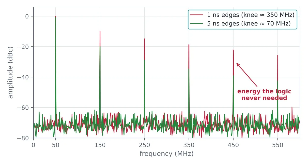
So the first question is whether you need that rise time at all. Most 50 MHz logic is perfectly happy with a 3 to 5 ns edge, and slowing the edge pulls the spectral knee down by the same ratio, which starves every resonator on the board of the energy it was feeding on. A series snubber resistor at the driver is the cheapest way to get there, and a value in the 22 to 33 Ω range is a common starting point. The resistor works against the trace and load capacitance to roll the corners off the edge, and it damps the reflections and ringing at the same time. You are giving up speed the logic never needed and buying back margin it did. This is also why stub problems sneak onto boards that nobody thinks of as high-speed, because a slow clock with fast edges rings the same bottles a gigabit link does.
The drill bit is a filter component
The fix for a resonant cavity is to not have one. The technique is called back-drilling. After plating, a slightly oversized bit re-enters the via from the far side and bores out the unused length of barrel, leaving copper only where the signal actually travels. You are removing the bottle, not muffling it.
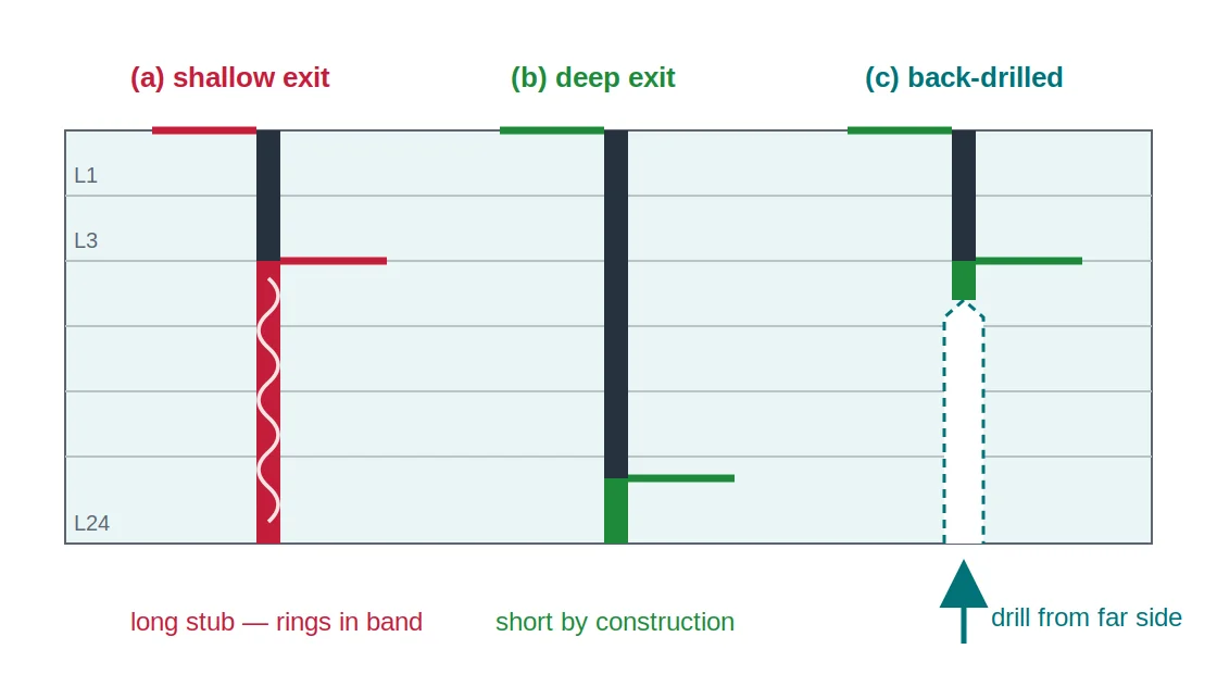
On press-fit connector fields, which is where the trouble usually lives, three things earn their place on the checklist.
- Leave enough barrel to hold the pin. A press-fit tail needs plated barrel to bite into, because the interference fit is the connection. Back-drill too enthusiastically and you've traded a signal-integrity problem for a mechanical one, which is not the direction of progress. Check the tail length, leave a healthy margin of barrel (a few tens of mils is common practice) and drill to the first signal layer below that.
- Or route low and skip the drill. The barrel requirement is why backplane designers so often put power on the upper layers and run the fast signals down low, since a deep exit leaves a short stub by construction. Some backplanes get away with no back-drilling at all, not because stubs stopped mattering, but because the routing discipline never built the bottle in the first place.
- Fix the via impedance while you're in there. The big drills that press-fit pins demand drag the via impedance well below 100 Ω differential no matter what you do. Enlarged antipads, shaped like racetracks around each pair, claw some of that back. Antipads and back-drilling work together, and either one alone leaves margin on the table.
Summary
A 10GBASE-KR backplane came up with intermittent link errors, and the errors tracked exactly one variable: the layer where each signal exited its via. A shallow exit leaves a long stub of unused via barrel below the trace, and a long stub is a quarter-wave resonator that notches the very band the link is transmitting in. The rule of thumb is to keep via stubs under about 30 mils at 10 Gbps, and ours were roughly three times that.
The fixes are not exotic. Back-drill the unused barrel, and leave enough plating to hold the press-fit pins. Route the high-speed signals on lower layers so the stub is short by construction. Improve the connector via impedance with enlarged racetrack antipads, because antipads and back-drilling work together. We made the changes on the next spin, and the counters went to zero and stayed there. The cheapest filter on your board is the one you didn't know you installed.
Field notes
- Intermittent link errors that correlate with route layer point at via stubs before anything else. Pull error counters per port and sort by exit layer; it's a free experiment.
- Keep via stubs under about 30 mils at 10 Gbps, and tighter as rates climb.
- Back-drill, but leave enough plated barrel for the press-fit interference fit, then drill to the next signal layer down.
- Better yet, route the fast signals on lower layers so the stub is short by construction, and let power live up top.
- Press-fit connector vias run low-impedance by nature. Racetrack antipads recover margin, and they pair with back-drilling rather than replace it.
- Ground-stitch every layer transition within about 25 mils, and keep solid ground on both sides of high-speed routes.
How this was written
This started as a conversation. I guided all of the content: the failure, the error counters, the root cause and the fixes come from a real 10 Gbps backplane bring-up and the signal-integrity review that confirmed what the data was saying. My friend Claude, Anthropic's AI assistant, did most of the typing. The bottle is mine. Any errors are mine too, and this time they're the kind you can count.
References and further reading
- IEEE Std 802.3, Clause 72: the 10GBASE-KR physical layer specification.
- Eric Bogatin, Signal and Power Integrity — Simplified, 3rd ed., Prentice Hall, 2018: via stubs, resonance, and back-drilling fundamentals.
- Howard W. Johnson and Martin Graham, High-Speed Signal Propagation: Advanced Black Magic, Prentice Hall, 2003: transmission-line behavior of vias and connectors.
- Donald Telian, Signal Integrity, In Practice: A Practical Handbook for Hardware, SI, FPGA & Layout Engineers, 2022 (siguys.com).